EXAMPLE PENDULA
1. Support constrained, 2. Long-Period Physical, 3. Optically Driven, 4.Cavendish Balance,
5. Multi-Purpose Chaotic, 6. Modified Analytic Pan Balance, 7. Torsion-Gravity, 8. Tiltmeter,
9. Leaky, 10. Automated Kater, 11. Servo, 12. "Non-adjustable High Precision Kater ,
13. Soup-can viscosimeter 14. Rod Pendulum 15. Flex-Pendulum
(Motions monitored in all cases with some form of SDC Sensor)
The first pendulum to be outfitted with doubly differential capacitive sensors was a support constrained pendulum. In the absence of damping, the resulting "Hamiltonian" system can exhibit chaotic motion. A paper which describes this study is, "Chaotic motion from support constraints of a nondriven rigid spherical pendulum", Phys. Rev. A 38 (10), 5352 (1988).
This pendulum was also used to produce beautiful artforms, the example provided here being a jpeg of size about 60K. The trace was produced by connecting the SDC sensor of the pendulum to an x-y recorder and letting the pen follow the motion of the pendulum in free decay.
(Another example of artwork generated by this pendulum.)
Soon after Peters' Physical Review paper appeared in 1988, commercial versions labeled 'oak and brass' became available through mail order houses. Such a pendulum was responsible for recent international excitement, after recording an artistic 2-D image of the Seattle earthquake. The APS News said the following about the trace:
'Images of the unusual pendulum pattern were distributed over the Internet, and quickly spread around the world. MacLeod, who posted the images on his Web site (http://www.gaelwolf.com/pendulum.html), has received thousands of letters from people theorizing about what the shape might mean: the eye of Poseidon, a rose, or even (for conspiracy buffs) a recording of a top secret government weapon designed to trigger earthquakes.'
The long-period physical pendulum was the first pendulum to demonstrate the unexpected low level features characteristic of mesoanelastic complexity.
The optically driven pendulum was researched by cadets at the United States Military Academy, West Point, New York. The lithium fluoride single crystals were exposed sequentially to an ion argon laser beam (cw), using shutters. The shutters were opened according to a square wave drive of adjustable frequency. Driven by thermal expansion due to absorption of the beam by first one and then the other of the crystals; the pendulum drive could be swept in frequency from below to above resonance. Capable of demonstrating a variety of fascinating mesoanelastic phenomena, this system is described in the paper by cadets Coy and Molnar: "Study of material structures using an optically driven physical pendulum", PH489: Advanced Independent study in Physics, 1996. Additional information is to be found in the proceedings of the1997 National Conference on Undergraduate Research, Austin, Texas. The abstract of the published paper reads as follows:
A physical pendulum with adjustable period has been studied in free decay, and also when excited at very low levels with a laser. Using a novel capacitive sensor to measure displacement, it was found that the motion of the pendulum depends significantly on the material properties of strategically placed samples, that are load bearing members of the pendulum structure. Placed in pairs, on opposite sides and near the center of mass; the samples, under compression, are exposed sequentially to the laser. Differential thermal expansion causes periodic lateral shifts in the center of mass, which is the driving mechanism. The frequency of the laser drive is adjustable, by means of an electronic timer connected to shutters. For samples of single crystalline lithium fluoride, the motion involves complicated hysteresis. Moreover, the damping constant can be negative, meaning that the pendulum oscillates as a result of stimulated processes involving defect structures of the LiF.
One of the most successful applications of SDC sensors has been to the Cavendish balance, which is a torsion pendulum. By using two sensors connected in electrical phase opposition, the otherwise troublesome pendulous modes of the torsion balance are nearly eliminated. TEL-Atomic, Inc., of Jackson, Michigan sells this user friendly balance.
![]()
Tom Martin, of the Gravity Research Institute in Boulder, Colorado, has used the balance to obtain EXPERIMENTAL EVIDENCE AGAINST REPULSION IN HOLLOW SPHERICAL SHELLS. His pdf paper on this work is to be found on the web at: www.gravityresearch.org.
The following quote is taken from Tom's paper: "The Tel-Atomic torsion balance is manufactured primarily as a pedagogical device, but our experience with it has demonstrated that it is also a very good research tool. For detailed information about the balance, see http://www.telatomic.com/sdct1.html ."
Note: Prof. Matt Marone has connected one of these pendula to the internet, using LABview. Not only are various state variables available for web viewing, control of the drive frequency is possible.
This commercial instrument is sold by TEL-Atomic, Inc. It may be used to study the rigid planar (simple) pendulum in all of its distinctly different and interesting regimes: (i) harmonic oscillator approximate, (ii) nonlinear, but not chaotic, and (iii) chaotic. Using it, a previously un-noticed category (ii) mode was discovered, which has been labeled the "bell-ringer" mode. To sense the motion of this pendulum, a velocity detector is employed in which two rare earth magnets are placed on a Be-Cu cantilever and positioned on opposite sides of an aluminum disk mounted on the motor shaft which is the axis of the pendulum. The pendulum drive is by means of an induction motor. Details of the system are provided in the 140 page monograph, Mechanical System Dynamics, with an introduction to Chaos and Complexity which is supplied with the TEL-Atomic hardware. The total package includes about 40 software simulations, the executables of some of these being available for download from Dr. Peters' homepage.
6. MODIFIED ANALYTIC PAN BALANCE
For this instrument, a chemical analytic balance was modified. A secondary knife edge was added to accommodate length changes in the wire specimen which was held in tension by the two outriggers which were also added at the boom ends. One of the more interesting studies involved the addition of a solenoid to surround an iron wire sample. Following demagnetization of the sample, a variety of unexpected behaviors were noted. The decay of the system in one case was according to a linear rather than logarithmic decrement. Sometimes bistable changes in length could also be stimulated.
In the torsion-gravity pendulum the restoring torques of torsion and gravity act in opposition. Unlike the ordinary pendulum which requires motion past vertical (winding modes) for chaos to be possible, the torsion-gravity pendulum is capable of chaotic motion at fairly small amplitudes. By operating with the restoring torques of torsion and gravity in opposition, a double-well potential function is appropriate to the description of the motion at lower levels of the motion. If allowed to "wind", the system would be a mechanical analogy to certain forms of the Josephson junction. This pendulum was treated in "Chaotic pendulum based on torsion and gravity in opposition", Amer. J. Phys. 63 (12), 1128-1136 (1995).
The tiltmeter is a torsion pendulum having some similarities to the torsion-gravity pendulum, however it is designed to operate away from the double well of the latter. The amount of gravitational opposition to the torsion is controlled by the angle of inclination of the torsion wire with respect to the local gravitational field. As the angle approaches a critical (unstable equilibrium) point, the sensitivity of the instrument to secondary tilts (at right angles to the inclination) can be made large. The principles of operation can be found in, "Mechanically adjustable balance and sensitive tiltmeter", Meas. Sci. & Tech. 1 (11), 1131 (1990).
The combination of both high mechanical amplification, as well as high electronic sensitivity by using an SDC array, permits this instrument to measure many interesting modes of earth vibration. For example, the instrument has been used to study free earth modes which result when a rapid internal relaxation of the earth occurs while under the influence of tidal stresses. A paper which describes some of these observations is the J. Korea Phys. Soc. article: M. H. Kwon & R. Peters, "The study of eigenmode types and source nonlinearity in the free earth oscillations" Saemulli Vol. 35 no. 4, 569 (1995).
Unlike a horizontal seismometer, which also responds to tilt, this instrument is not sensitive to localized disturbances, because the center of mass is made purposely close to the axis of rotation. By contrast, there is a long distance between the axis and the center of mass of the conventional instrument, so that it is very much influenced by local accelerations. Additionally, whereas the conventional instrument is usually operated with damping (sometimes near critical), the present tiltmeter takes advantage of improvements in signal to noise ratio that come from characteristics of stochastic resonance as the instrument operates with little damping. High frequency noises, which result as the rotor "skates" among metastabilities borne of anelasticity in the torsion wire, are filtered by means of autocorrelation.
(Additional information contrasting this instrument with more conventional tiltmeters and/or horizontal seismometers is to be found in the following web article).
Pictures of the Tiltmeter:
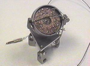
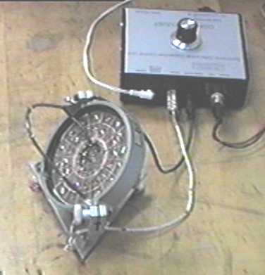
Fabricated to fit in a front-surface mirror (optics) holder, the compact size of the instrument can be appreciated by comparing to the standard phonojack plug also picutured. This jack and another subminiature one plug into the SDC electronics support, shown in the second picture.
This tiltmeter is now being used, along with an SDC outfitted WWSN (Sprengnether) vertical seismometer for the study of earth motions, especially free earth eigenmodes. Results from these novel earthwave instruments should be especially interesting to the geophysics community.
In the study of a leaky pendulum a fluid (water or alcohol) was allowed to drip out of the faucet at its bottom, while it was swinging. For some, the variation of period as a function of time is counter-intuitive. It is described in "Motion of a leaky pendulum", Amer. J. Phys. 62 (2), 137-139 (1994).
An SDC sensor permitted the rapid measurement of the period of this Kater pendulum by means of Lissajous figures. The reference signal for the Lissajous display was synthesized by the computer. Details are to be found in "Automated Kater Pendulum", Eur. J. Phys. 18 217-221 (1997).
This servo pendulum utilized the first generation of doubly-differential capacitive sensors, which was labeled linear rotary differential capacitive transducer (LRDCT). Because the restoration (drive) torque in this instrument is proportional to the square of the drive voltage and the output sensitivity is proportional to the first power of the same voltage, it is possible to build a nonlinear servo pendulum in which the same transducer acts as both actuator and sensor. The prototype which was studied is described in "Capacive servo-device for microrobotic applications", J. Micromech. Microeng. 1, 103 (1991).
12. "Non-adjustable" High Precision Kater Pendulum
With a "non-adjustable" Kater pendulum in which the periods about the two axes have been made almost equal by computer design, one can simply measure the Earth's gravitational field (g) to a few parts in 10 thousand.
The soup-can pendulum is an interesting example of the importance of internal friction to pendulum damping. Most people erroneously believe that virtually all pendula are damped by the external forces of either air or knife edge. For long-period pendula, the damping is due primarily to internal friction from flexing of the principal components of the load bearing structure. Even when knife edges are important, it is the internal friction within either the knife or the surface on which the knife rests that is mainly important. This has been shown, for example, by letting the knife edges rest on PZT wafers, where the damping is an order of magnitude greater than when resting upon other comparably hard surfaces such as steel or sapphire. As in all cases of such internal friction, the dominant mechanism is the rearrangement of defect structures.
The soup-can pendulum provides a fascinating challenge to one's intuition; in that the damping tends toward zero as the viscosity of the enclosed fluid tends either toward zero or infinity. The reason becomes obvious with a little thought. When the viscosity is very low, there is insignificant coupling (small energy exchange) between the can and the fluid; as the fluid undergoes negligible rotational oscillatory motion (w.r.t an inertial frame). Contrariwise, when the viscosity is very large, the coupling is so great that the motion of the two systems are almost completely correlated. Only intermediate values of the viscosity permit both large relative motion and significant momentum transport (energy exchange) to result in significant damping.
This pendulum is referred to as a viscosimeter because it is very well suited to measuring the viscosity of liquids. For example, one could measure the viscosity of a motor oil by simply filling the can with the oil of interest.
A paper which has provided nice agreement between theory and experiment for the soup-can pendulum is one that was submitted to the Amer. J. of Physics in 1997 but was judged by the editors to be of little interest to educators. To the contrary, the last few years have suggested that this novel system is of great interest and value to students of physics. You be the judge of the following paper, titled "Soup-can Pendulum"--and please let me know your opinion.
14. Rod Pendulum
Consider a rigid rod pendulum of length L, having uniform mass density. The moment of inertia about the center is Ic = ML 2 /12. The parallel axis theorem provides the moment for an axis at a distance x above the center, I = Ic + M x2. When oscillating about an axis at x above the center of mass, the torque of restoration is Mgx q for small angle q. Thus the equation of motion, ignoring damping, is that of the simple harmonic oscillator
I d2q/dt2 + Mgx q = 0. From this well known equation, the resulting period of the motion is seen to be T = 6.2832 [(x2 + L2/12)/(gx)]1/2 .
Conventional wisdom would try to describe this system, with damping, by adding to the equation a term, c dq/dt, with c being constant. Unfortunately, no pendulum is ever this simple. For example, the damping term must necessarily be nonlinear. See, for example the paper, "Creep and Mechanical Oscillator Damping."
The rod pendulum has been studied as x goes toward zero, using pendula made out of malleable metal alloys. Alloys do not strain smoothly because of the Portevin Le Chatelier effect, and so these pendula exhibit complex behavior. The results are described in the paper, "The Pendulum in the 21st Century--Relic or Trendsetter?".
15. Flex-Pendulum-- ( view as HTML ) basis for an Improved Timepiece
A compound pendulum can be configured, because of elastic flexure, to have period dependence with amplitude that is opposite to that of an ordinary pendulum. Careful tailoring of the instrument permits compensation over a large amplitude range. For example, the linked paper shows that is is theoretically possible to have virtually isochronous motion for amplitudes less than or equal to 90 degrees.
Return to homepage.