SDC SENSORS
Allan Coleman of Edmonds, Washington has built (latest vertical broadband seismometer) an insturment using the SDC sensor with a Willmore spring.
Allan built a force-feedback broadband horizontal seismometer, the sensor of which is a gap-variable SDC sensor.
Mesodynamics research, featuring "low and slow" (small amplitude, long period) mechanical oscillators, has been possible because of the sensor technology invented by Dr. Peters (U.S. Patent No. 5,461,319).
A recent MEMS use of the SDC technology-- Micro Inertial Measurement System. Work by a Singapore group.
Also, Fully-Differential Switched Capacitor circuits: " .... to perform high dynamic range analog circuits." (A MEMS-based rotational accelerometer
for HDD applications with 2.5rad/sec2 resolution and digital output, A. Gola, et al)
Michael Barker's microscope is evidently in the process of being marketed (c.f. Design and operation of the Scanning SQUID Microscope).
The specs include the following: Position sensing Method: Capacitive, full-bridge differential technique.
Sensitivity: Equivalent to 1.5µm Hz-1/2 for 1V pk-pk drive voltage.
Linearity: Better than 0.1%. Easily correctable to better than 0.01%.
Features: This particular sensor has an additional output for rotation of the moving plate. This rotation output has a sensitivity of around 10 arcseconds Hz-1/2.
He has done some excellent physics of computational type as well, showing that ".... the slight deviations from linear of such [SDC] devices are due to the fringing fields around the edges of the electrodes and not, as previously thought, due to imperfections in the machining of the electrodes. This data enabled me to publish a paper documenting this novel capacitive position sensor." Dr. Barker showed this by solving Laplace's equation numerically. (see the section titled, "Capacitance Position Sensor").
The SDC physics was employed by University of Maryland researchers to build a "Capacitive sensor for micropositioning in two dimensions" (physics-183.umd.edu/people/paul/capsen.pdf) . (see reference 10 of the Rev. Sci. Instr. article by P.W. Kolb, R. S. Decca, and H. D. Drew)
In their paper, "Investigation of the relation between stress evolution and surface deformations in high dose MeV energy He implanted Si", (Proc. of the Ninth Int'l Conf., Ion Beam Modification of Materials,Canberra, Australia, 5-10 February, 1995, p. 828-831); Hungarian researchers Hajdu, Fried, and Paszti, state the following concerning their use of the SDC sensor: "This method was chosen because it is a simple, yet sensitive arrangement that reduces the problems of stray capacitance and oscillator stability that often caused concern in previous experiments. .... For more details on this universal device, see .... " (Rev. Sci. Instrum. 64 (1993) 2256.)
The SDC technology is also ideally suited to scanning tunneling microscope applications, as recognized years ago by Dr. Peters and his colleague Dr. Roger Lichti; however, manufacturing capabilities at Texas Tech University did not permit that development at the time. In February of 1999, it became clear that Hewlett-Packard has recognized the value of the SDC sensor in this arena, being assigned the patent "Position detection device" , US Patent No. 5,861,754. No doubt this patent, the heart of which is an SDC sensor--was awarded because the developers could bypass an "appendix" to Peters patent title--"employing cross coupled conducting plates to form equipotential pairs"--that was required by the examiner before Peters' patent would be awarded. The original title presented by Peters to the U.S. Patent Office was "Symmetric Differential Capacitive Transducer". Had the original title been allowed, it is likely that the Hewlett-Packard patent could never have been rightfully awarded, since the essential technology of their claims is that due to Peters.
The Hewlett-Packard patent is a strong endorsement of the SDC sensor, especially because their description of the technology, such as the following--authenticates previous claims by Dr. Peters:
".......since all of the capacitors constituting the AC bridge are variable capacitors, the invention provides a position detection device that has a smaller shape and improved sensitivity compared to conventional electrostatic capacitance position detection devices. Since all the capacitors of the AC bridge are variable capacitors, the position detection device is insensitive to position changes in the two directions orthogonal to the detection direction. Since all the capacitors of the AC bridge are variable capacitors, the position-indicating signal varies linearly with the relative position between the stage integrated circuit and the probe integrated circuit. The position detection device has the further advantage of being easy to manufacture, since the capacitor electrodes can be formed on the surface of an integrated circuit using standard integrated circuit fabrication technology, and position detection circuit can be simultaneously fabricated in the integrated circuit using similar fabrication techniques.
Others in the sensor world have begun to appreciate the SDC technology. It was included in a book published by Technical Insights/John Wiley and Sons, "Test and Measurement: A Definitive Guide to Sensor Developments and Opportunities (R416; ISBN 0471-34984-4: 175pp.; 12/98). The section of the book dealing with Peters' work is titled "Contactless Sensing Measures Small Displacements", p. 90.
Advantages of the earliest form of the SDC sensor ("linear rotary differential
capacitive transducer") were recognized by Ford Motor Company, who
provided financial support for some of the early studies. Automotive
applications abound, and one case that has been examined (to include
proof-of-principle testing with prototype hardware) is that of an
electric power assisted
steering (EPAS) system.
SDC stands for symmetric differential capacitive sensor.
It is a full bridge sensor that is sometimes called doubly differential.
Still another name is "fully differential". Years after the first
paper pointing to the advantages of fully differential capacitive sensors,
the microelectromechanical systems (MEMS) world is finally discovering it.
The first example to be easily found on the WEB is that of the Berkeley
Sensor and Actuator Center; who published on their work, "A
micromachined
fully differential lateral accelerometer' in 1996. Professor Fedder's
group at Carnegie Mellon University has published
also--"A
lateral capacitive CMOS Accelerometer with Structural Curl Compensation"
. These papers repeat what has been oft-inferred if not specifically
stated in earlier publications concerning the higher symmetry sensor--
"...double the sensitivity of half-bridge topology with the same value
of sensing capacitance. Since the interface is truly fully differential,
very high CMRR can be achieved at the outputs." Unfortunately, the
authors apparently overlooked the fully differential capacitive sensor
publications of Peters. In this 'information age' of the WEB, it is
hard to imagine such an oversight!
The archetype is a linear position sensor, based on area change. Another example is the pressure sensor which works via gap spacing change.
In all cases, the equivalent circuit is that of a full-bridge, and the electronics is based on synchronous detection.
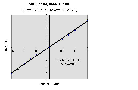
An alternative electronics configuration is one which uses diodes instead of a conventional synchronous (lock-in) detector. Ideally, the oscillator should be bipolar, and the instrumentation amplifier can in some cases be omitted, the output being directly connected to a voltmeter or chart recorder. The performance of such a simple diode system can be surprisingly good, as shown in the following example.
One of the most successful applications of SDC sensors has been to the Cavendish balance, which is a torsion pendulum. This instrument is manufactured commercially by TEL-Atomic, Inc., Jackson, Michigan.
If output impedance were not a consideration, the sensitivity of an SDC sensor would be inversely proportional to the width of the moving electrode. Unfortunately, as this dimension is shrunk toward zero, the resulting increase in the output impedance causes the sensitivity of the unit to go ultimately to zero. By using an increasingly larger number of individual sensors in parallel, as the size of each moving component is reduced; the sensivity can be made to increase. Two examples are provided: an array for linear position sensing, and one for angle sensing. The latter is used in the tiltmeter mentioned elsewhere.
UNLIMITED RANGE INSTRUMENTS
By using two SDC sensors properly separated, it is possible to realize an unlimited range sensor. The example provided is one designed for linear position sensing, but an angle measuring instrument is described in "Capacitive angle sensor with infinite range", Rev. Sci. Instrum. 64(30, 810 (1993).
The SDC sensor has been used in a variety of mechanical oscillator studies, some of which are non-classical pendula. An array of SDC type was used in the 'Electric Power Assisted Steering' prototype built as a senior design project by Mercer Mechanical Engineering students.
A variety of instruments have been developed around this sensor. These include the
(1) "Computerized Cavendish Gravitation Balance" which is sold by Tel-Atomic Inc. and also Central Scientific Company. This state-of-the-art instrument is the heart of one of the first six NASA Breakthrough Propulsion Physics grants.
(2) A Multipurpose chaotic pendulum sold by Tel-Atomic Inc., which is the first online interactive chaotic pendulum of hardware, rather than simulation type.
(3) A miniaturized accelerometer based on the SDC technology (mesoscale using PC boards) is being developed by Auburn University's 'Laboratory for Electronics Assembly and Packaging = LEAP'. .
(Center for Advanced Vehicle Electronics) under contract to the United States Army.
(4) SDC sensors employing LABVIEW algorithms in place of traditional Phase Sensitive Detector electronics are being used to measure
strain in pig tissue samples as a function of temperature. The project is of importance to heart valve replacement in humans and is the
senior project work of three Mercer Biomechanical Engineering students.