SYMMETRIC DIFFERENTIAL CAPACITIVE (SDC) SENSORS--A tutorial
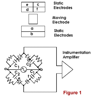
One configuration of the transducers, consisting of two parallel printed circuit boards to comprise a full bridge, is illustrated in Figure 1, where the top part of the figure shows the parallel adjacent plates (static electrodes) separated for ease of explanation. The bottom part of the figure (equivalent circuit) shows electrode connections, including the oscillator input and the amplifier output. The indicated resistors and diodes provide for a d.c. output. Mechanical movement is detected according to the position of the grounded moving electrode, which does not contact the static plates located on its opposite sides.

For the SDC sensor, capacitors on opposite sides of the bridge are always nominally equal, independent of the position of the moving electrode. (The sensor is sometimes referred to as 'doubly differential', 'fully differential', or as a 'fully active' capacitive bridge.) For the position of the moving electrode shown in Figure 1, the bridge is balanced and the output is zero.
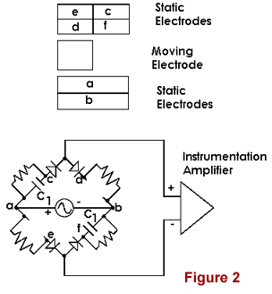
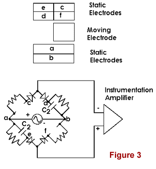
To understand how the sensor works, it is convenient to consider two extreme cases--moving electrode at its far left, as in Figure 2 and conversely at its far right, as in Figure 3.


For the discussion which follows, keep in mind that it is not possible to induce charge through a Faraday shield; i.e., the moving electrode 'shields' various parts (areas) of the a/b electrode set from the c/d/e/f electrode set. In Figure 2, capacitive coupling between each of a/e and b/d has disappeared--assuming that fringe fields can be ignored; which is a good approximation for the gap spacings normally used in the sensor. For the indicated polarity of the oscillator, the output from the instrumentation amplifier is positive (assuming the top line to be the non-inverting input). When the oscillator polarity reverses one half-cycle later, it is seen that the two diodes which retain capacitive coupling to the amplifier are reverse biased--so the output then becomes zero. Consequently, the output from the amplifier is a pulsating positive d.c. The ripple (pulsation) is removed by later stages of amplification (using op-amps).
In Figure 3, capacitive coupling between each of a/c and b/f has disappeared. Using the same arguments as in Figure 2, it is seen that the ouput from the amplifier is a pulsating negative d.c.
The computerized Cavendish balance uses two SDC sensors connected in electrical anti-parallel. This arrangement largely eliminates noise due to pendulous motions and thus overcomes a major limitation in the design of other manufacturers. To understand the mechanical common-mode feature of the TEL-Atomic design, consider the following: The boom which supports the small masses of the balance is also the moving electrode described above. The pair of SDC sensors are situated on opposite sides of this boom, which is supported at its center by the tungsten fiber. Ideal operation of the balance (inertial laboratory) is one that involves only rotation of the boom. Thus the ideal response corresponds to deviations that are simultaneously like figures 2 and 3 (except not extreme). In order for the outputs to be added, since one is positive and the other is negative; polarity must be reversed on one of the two amplifiers. Thus the electrical anti-parallel connection. Should there be motion of the boom in which both outputs are either negative or positive, because the boom is swinging as a pendulum; the response to this motion is significantly attenuated. The attenuation, which is a mechanical common-mode type, is analogous to electrical common mode attenuation in an instrumentation amplifier. The combination of both a mechanical common mode rejection and an electrical common mode rejection provide for an unusually user-friendly Cavendish balance.