
NOTE: The figures which follow were taken from the proposal submitted by the students.
Figure 1 illustrates, in general, how an electric motor can be used to provide power assist by means of electronic feedback involving a sensor, control unit, and motor.
Figure 1: Generic electric power assisted steering.
A cross section of part of the proposed system (torsion rod and sensor with associated components) is shown in Figure 2.
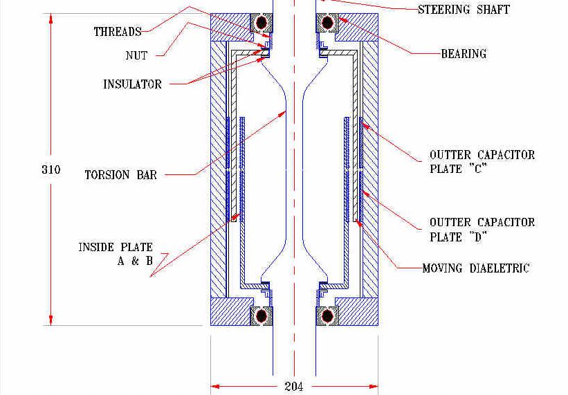
Figure 2: "Heart" of the present design.
In Figure 3 is shown one element of the 16-element sensor array which will be used to measure twist of the torsion rod.
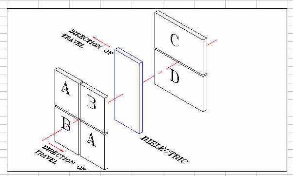
Figure 3: One element of the 16-element SDC sensor array.
The equivalent circuit of the element pictured in Fig. 3 is shown in Figure 4.
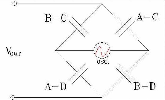
Figure 4: Equivalent circuit for an SDC sensor.
The geometry of the complete 16-element sensor is illustrated in Figure 5.
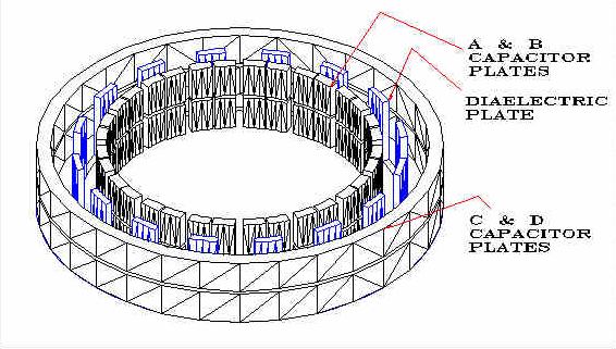
Figure 5: Sensor for the electric power assisted steering unit.