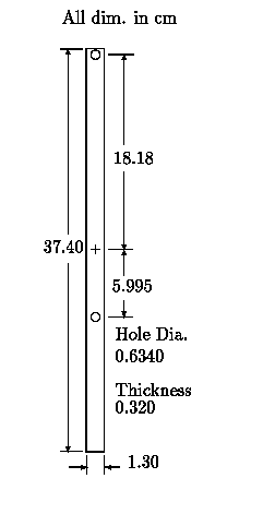
Figure 1: Student-Friendly Kater Pendulum.

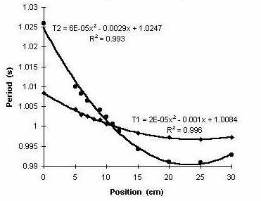
Figure 2: Variation of Period with binder-clip Position.

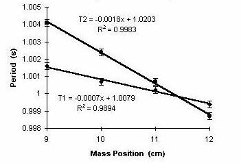
Figure 3: Enlargement of Figure 2 in the region of period matching.

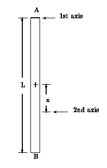
Appendix Figure 1: A `meter-stick' Kater pendulum.
With the information provided in this article, students should be able to
easily measure the acceleration of gravity to a few parts in ten-thousand
in one two-hour laboratory period. This degree of precision is one to two
orders of magnitude better than can be achieved with the usual simple pendulum
under comparable conditions. The instrument described is a ``simple'', slightly
adjustable Kater pendulum that students skilled in machine work should be
able to build for themselves. The two axes of rotation are provided by holes
that are drilled through the rectangular brass unit to receive a small knife
edge. Period adjustment is provided by changing the position of a pair of
small binder clips.
Some ``Background''
Virtually everyone who has taken a physics course knows that a pendulum can
be used to measure the Earth's gravitational field; i.e., the acceleration,
g » 9.8 m/s2.
It is not widely known, however, that a naive pendulum measurement will not
show variations in g from one place on the Earth to another. For example,
the altitude must increase from sea-level to 3000 m
» 10,000 ft for g to decrease
by one part in a thousand. Similarly, the extreme sea-level global variation
with latitude and/or longitude is only about five parts per thousand. Because
gravity differences over the earth's surface are very small, geophysicists
have used the milligal (10-5 m/s2) to state
differences. In these units, going from the equator, where the mean value
of g = 978,049 to the poles, g increases by 5,172
[1]. The reference for these gravimeter
(relative) based values is the absolute g experiment that was performed with
six Kater pendula in Potsdam Germany (latitude
52° N® 981,274)
in the early part of this century.
The pendulum has long been a favorite instrument for measuring the acceleration
of gravity; however, it is not a trivial matter to measure g to better than
about one percent with a simple pendulum-one in which a concentrated mass
swings at the end of a flexible cord. The biggest challenge in this case
is the accurate determination of the distance from the support to the ``center''
of the pendulum [2]. To obtain accuracies
in the vicinity of 1 part in 104 has typically required a long
pendulum. This has disadvantages because, as the length of a pendulum increases,
it is increasingly susceptible to noises, both from surrounding air and also
from the support which is never completely inertial. An appreciation for
the physics involved in the multiplicity of correction terms required of
such an experiment can be found in the paper by Nelson and
Olsson[3]. Fortunately, the corrections mentioned
in that paper, such as buoyancy and added mass of the air are not required
for present purposes.
The Kater Pendulum
Many of the difficulties of the simple pendulum are removed by working with
the pendulum first considered by Captain Henry Kater in 1815. Being
``reversible'', the Kater pendulum oscillates about either of two axes. In
conventional form (such as the unit sold by Cenco), there is either an adjustable
knife edge or a moving mass which is positioned, ideally, so that the period
of the pendulum is the same about the two pivots. When the periods are matched
so that T1 = T2 = T, it is
easy to show [4] that T =
2pÖ{[(l)/
g]}, where l is the spacing between the two axes. Thus the system
is equivalent to a simple pendulum of length l. Since l can
be measured with relative ease to a few parts in 104, the Kater
pendulum is thus attractive as a means to accurately measure g.
For those not familiar with the Kater pendulum, a pedagogical example using a meterstick is provided in the Appendix. The theoretical estimated period obtained there (T = 1.6 s) can be easily compared against a crude experiment. Simply hold the meterstick between the finger nails of thumb and middle finger and measure with a stopwatch. The large damping demonstrates that this ``system'' is not practical for a precise measurement of g. The same proves true when one tries to provide axes of rotation by using sharpened pins that barely press into the stick. Additionally, small circular rods inserted through the stick to serve as axes also were found to be unsatisfactory.
Present Instrument
The conventional Kater pendulum is difficult to use, partly because the range
of period adjustability is usually quite large. To design the user-friendly
pendulum shown in Figure 1, the computer was necessary. The overall length
of L = 37.40 cm was chosen so that the period would be nominally
1 s, for rotation about each of axis 1 (an end), and axis 2, a point
» 0.67×37.4 cm away from axis 1.
For a uniform rectangular physical pendulum of length L, having small width
and thickness compared to L, it is shown in the appendix that T =
2pÖ{[2 L/
3 g]}. Of course, the practical challenge is one of providing suitable
axes. In the present case, this was accomplished by means of two 1/4 in
diameter holes whose centers were drilled at the indicated positions, relative
to the midpoint of the pendulum. Because the introduction of these holes
results in a more complicated geometry, as compared to the idealized case
just described; their placement was determined via computer, using the parallel
axis theorem and recognizing the hole as having negative mass.
The knife edge
The knife edge was produced from a small piece of carbon steel, of the type
used for cutting tools in a lathe. The starting stock was of square cross
section, 0.25 in × 0.25 in, about 1 in long.
It was ground on one end to an ``edge'' with the interior angle between planes
roughly 30°. To hold the pendulum,
the unground end of the piece was clamped between the jaws of vice-grip pliers,
which was in turn clamped to a conventional laboratory stand. For the brass
unit described above, the log-decrement of the motion was small enough that
the motion of the pendulum could still be visually perceived 30 min
after initiation of motion. It should be noted that a rigid support of the
knife edge is called for, since a flimsy one will both lengthen the period
and increase the log-decrement.
Period Adjustment
Typically, there are two ways that period adjustment is accomplished in a
Kater pendulum-either (i) moving the position of one of the pivots, or (ii)
changing the moment of inertia by altering the mass configuration. For the
present pendulum, the latter method has been used.
To change the period around the nominal 1 s value, a pair of small binder
clips were used, each of mass 1.2 g, which is small compared to the
pendulum mass of 129.3 g. These clips are the ordinary black spring
metal type used to bind documents that are too thick for a paper clip. A
pair was chosen, rather than a single clip, for positioning on opposite sides
of the pendulum. Thus the center of mass of the system remains on the line
of symmetry of the pendulum. Operationally, the clips are moved in increments
of 1 cm starting near one end of the pendulum, and advancing toward
the other end, measuring the period about each of the two axes for a given
position of the clips.
Timing
Period measurements were made using a standard photogate with the Precision
Timer (Vernier software) system sold by Pasco, for their CI-6510 Signal
Interface. The beam of the photogate was positioned vertically at the midpoint
of whichever hole was not being used as an axis. The horizontal position
was selected such that the beam was interrupted by the small segment of brass
between one side of the pendulum and the near edge of the hole. For this
placement of the photogate, the period measured will be other than
» 1 s if the amplitude is unacceptably
large or small. Thus this arrangement proved useful in determining the onset
of non-isochronism (amplitude large enough to increase the period through
nonlinearity). A 30 min comparison of the timer system against WWV showed
that the times displayed by the timer were uniformly slightly long, so all
data were corrected for this systematic error by dividing by 1.00038.
Results
Data collected with the pendulum are shown in Figures 2 and 3. Fitted to
the data, which were plotted with Excel, are quadratic fits for which the
R2 values are close to unity. For Figure 3, a linear least squares
fit was used, and the matched condition is one for which T =
0.9999 s. The abscissa in both graphs corresponds to the clamping
placement of the binder clips, with zero being near the end of the pendulum
which is opposite axis 1. Position 36 (unused) corresponds to the clips being
centered on axis 1 (top edge of the top hole).
Estimating g
Using the matched period value of 0.9999 s and the value of
l = 0.2481 cm, the acceleration of gravity in Macon,
Georgia was estimated to be
g =
4p2l/T2
= 9.797 m/s2.
Predicting the Uncertainty in g
Assuming random errors in the measurement of l and T, the relative
uncertainty in the acceleration of gravity is given by
dg/g =
[(dl/l)2 + (2dT/T)2]1/2. For our case, it was
assumed that the machinest [5] produced the
pendulum (on a milling machine) with all dimensions to the nearest
0.001 in. Thus the relative uncertainty in l is
dl/l =
1×10⁻⁴. The random uncertainty in the period measurement
(independent of the systematic error mentioned earlier, that was corrected)
was determined by taking 100 measurements at a few points and calculating
the standard deviation, which yielded dT/T
= 2×10⁻⁴. With these numbers, the uncertainty in g
is determined to be 0.003 m/s2.
Leeways
A low-mass wooden (Oak) pendulum was built and evaluated, expecting that
it would be a less precise instrument. It was fabricated ``crudely'' by cutting
to the requisite rectangular shape on a table saw. The width turned out to
be 1.25 cm, the thickness 0.42 cm, and the length 37.4 cm.
The holes for the knife edge support were drilled with an ordinary 1/4 in
bit. As compared to the clip mass total of 2.4 g, the mass of this pendulum
was quite small at 13.2 g (an order of magnitude less than the 129 g
brass pendulum). As expected, the timing errors proved larger, at approximately
3 ms- about an order of magnitude greater than those of the brass pendulum
at 0.2 ms. Additionally, the length was not measured as precisely-the
uncertainty being estimated at 0.2 mm. The variation of period about
the two axes proved similar in trend to that of the brass pendulum, except
the range of variation was much greater, as expected. About axis 1, as the
clips were moved from 0 to 34 cm, the period varied through a total
range of 87 ms, compared to 9 ms for the brass; likewise, about
axis 2, the total range was 0.42 s, compared to 36 ms for the brass.
With this wooden pendulum, the periods were found to match (from a linear
least squares fit) for the clips at 11.4 cm, yielding T =
1.003 s, and an estimate for the acceleration of gravity, g
= (9.77 +/- 0.05) m/s2. It was thus demonstrated
that a crude, low mass Kater pendulum can do as well as a decent simple pendulum;
although it is not recommended that such a pendulum be built.
Based on these results, it is expected that a reasonably good pendulum might be made of soft aluminum, cut with shears. It is recommended, however, that a metal of higher density, such as brass, be used; and at the very least cut with a bandsaw and then filed to shape. Preferably, these operations should be performed on a milling machine. Not only will this yield an instrument whose dimensions are closer to the nominal values indicated in Figure 1, but a separate measurement of the distance between the holes is then also unnecessary, assuming that the translating stages of the machine are properly calibrated.
Consider a uniform stick of length, L = 1 m, oscillating first about an axis at its upper end `A', as shown in the figure. Our problem is to find a 2nd axis, whose distance x from the center toward the opposite end `B', yields the same period as the 1st axis. Note that oscillation about this 2nd axis requires that the meter stick be turned upside down.
We now calculate the periods of the pair, starting with the 1st axis. The
moment of inertia of the uniform stick, with respect to its center, is
Ic = ML2/12 (assuming that both the width
and the thickness are much smaller than the length of the stick). For rotation
about the 1st axis at L/2 from the center; the parallel-axis theorem yields
I1 =
M(L/2)2 + Ic
= ML2/3. Thus, the period about the first axis is given
by
T1 =
2p Ö{1/3ML2/(1/2MgL)}
=
2p Ö{[2L/
3g]} =
2p Ö{[2/
3g]} »
2pÖ{[2/ 30]}
= 1.6 s.
Now let the meterstick be turned upside down from the 1st position and allowed
to swing about an arbitrary 2nd axis at distance, x, from the center toward
`B'. Here the moment of inertia is given by I2 =
M x2 + Ic, and the period is
T2 =
2p Ö{[(x2 + [1/
12])/ xg]}. Setting T2 = T1 yields the
quadratic equation x2-2/3x+[1/ 12]
= 0, which has roots x = 1/2 (non-interesting) and x
= 1/6, which is the Kater pendulum case. In particular, note that the
distance between the two axes is l = (1/2+1/6)L
= 2L/3. Thus, the meterstick Kater pendulum is described by
T = T1 = T2 = 2p Ö{[(l)/ g]} » 2p Ö{[(2/3)/ 10]} » 1.6 s.

Figure 1: Student-Friendly Kater Pendulum.

Figure 2: Variation of Period with binder-clip Position.

Figure 3: Enlargement of Figure 2 in the region of period matching.

Appendix Figure 1: A `meter-stick' Kater pendulum.