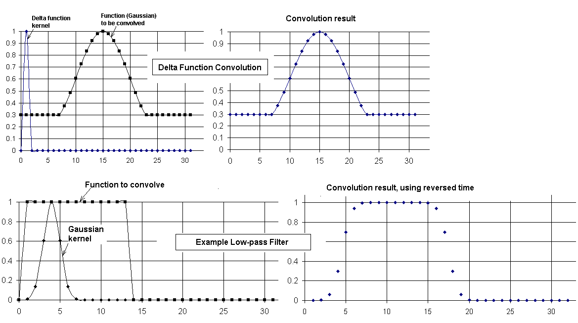
Figure 1. Example (top) of the convolution of a function with the delta function using a 32-point transform, and (bottom) low pass filtering as the kernel is widened.
Copyright 18 June 2004
ABSTRACT
Filtering of digital signals is accomplished on an Excel spreadsheet using fast Fourier transform (FFT) convolution in which the kernel is either a Gaussian or a cosine modulated Gaussian. Pedagogical examples of low-pass and band-pass filtering are provided, and the practical value of the spreadsheet is illustrated with some cases involving an earthquake record generated by a folded pendulum seismometer.
BACKGROUND
The FFT is a critical component of post processing of data. Although the `brute-force' calculation of the convolution of two functions is computationally prohibitive, the same is not true of the evaluation method based in the Wiener Khintchine theorem. The latter is one in which the transform of each of the two real functions is generated and their product (complex) then calculated. Their convolution is obtained simply from the inverse transform of that product. Although the generation of three transforms to filter a signal would be labor intensive when using the discrete Fourier transform (DFT), such is not true when working with the FFT given us by Cooley & Tukey [1].
These operations are easily performed with the Excel spreadsheet, which also allows valuable insight concerning characteristics of the filter thus generated. The pedagogical value of such studies should not be underestimated, since digital filtering involves esoteric mathematical operations surrounded by confusion. In the literature of the field, much is made of causality issues and the numerous methods employed to reduce the influence of Gibbs effect (`ringing' due to discontinuities). Thus, one encounters a host of different filters, whose characteristics are often described in relationship to the complex plane. Although poles and zeros are a natural means for treating steady state phenomena with the Laplace transform, it appears to this author that much of the common digital filter theory is misdirected. Attention to filter properties such as the `impulse response' appear to cloud, as opposed to clarify, the mathematics used to generate the filter. Evidently post-processor filter development has been greatly influenced by analog electronics hardware. Prevailing designs emulate popular real-time filters instead of optimizing the extraction of information from a previously sensed and recorded signal.
GAUSSIAN KERNEL
Filters can be described in terms of a `kernel' which apodizes the `raw' signal, a terminology purposely taken from the world of optics. There, image processing has made much progress toward optimal filtering of post-processed (two dimensional) signals. Although images are routinely filtered with kernels related to the Gaussian, it is mystifying the extent to which the Gaussian is not employed for one dimensional time series filtering. Personnel concerned with time series could profit greatly from a serious consideration of what has been learned through computer enhancement of photographs.
The Gaussian is one of the few functions whose form remains unchanged following transformation; i.e., the Fourier transform of a Gaussian is itself a Gaussian. This property is well known in physics, since it is the heart of the Heisenberg uncertainty principle. The essential feature of the uncertainty principle is the following. When a Gaussian is `compressed' (width decreased) in one space (such as time), it is `expanded' in the reciprocal space (frequency). In physics this property is frequently discussed in terms of a particle's position x and momentum p, where the product DpDx is a constant. In quantum mechanics we say that for conjugate variables x and p, the product of their uncertainties is equal to (or order of) Planck's constant h. This results because of the relationship between packet (deBroglie) wavelength l and momentum; i.e., p = h/l = hk/(2p), or `hbar¢k. The same is true of conjugate variables involving energy and time; i.e., DEDt » h. An example of the utility of this latter relation is its use to estimate life-time broadening of spectral lines.
The Heisenberg principle is a natural consequence of the mathematical nature of the Gaussian function, which is expressible as
|
(1) |
Its width is determined by c2, and frequently the function is normalized by the choice of c1 so that the integral of the function over all time equals unity. In the present work, where the Gaussian is used as a kernel, we instead set c1 = 1 so that the maximum value of g is unity. (Note. If the Gaussian expression above were a statistical density function describing variates in time, then the mean value of the distribution would be t0, and its standard deviation would be inversely proportional to c2. With the first-mentioned choice of c1 it becomes the normal distribution, especially important to statistics because of the central limit theorem. It is this author's belief that the Gaussian may be similarly important to the world of digital filtering.
Let the width of g(t) be specified by Dt, which (for statistics) is twice the standard deviation about the mean at t0. The Fourier transform yields the Gaussian G(w), naturally expressed in terms of the angular frequency w = 2pf. Factors of 2p are unavoidable with the Fourier transform. As opposed to finite difference approximations to the FFT, its definition naturally involves 2p, both in the argument of G and also as a multiplicative constant of the exponential. The latter as a normalizing factor can be associated with one or the other of g(t) and G(w), or it can be `dissected' in terms of its square root to be shared between g and G. Consequently there are six different acceptable forms of the Fourier transform. Individual users sometimes believe (unwittingly) that their version is the only acceptable one.
After calculating the width of the reciprocal-space Gaussian (Dw, with w = 2p f), one discovers (to within a factor of 2) the following identity:
|
(2) |
In similar manner, if working with x rather than t, then DkDx = 2p. The `k' of this relation, common in optics, is sometimes called `spatial frequency'. When part of wave phenomena k is called the `wave vector'. Its direction is that of the wave propagation, and its magnitude is k = 2p/l.
CAUTION-Excel Subtleties
It is important to understand that typical FFT algorithms (including that of Excel) ignore normalizing factors. Consider the FFT of an A column g(t) of real data of length N, the result G(w) being placed in column B. If one takes the FFT of column B (inverse transform) then column A is not recovered exactly; rather, (i) there is a `remapping' of the components, equivalent to reversing the time and shifting by an index value of `1'. Second, (ii) each component of B is larger than the corresponding component of A by the multiplicative factor N. Also, (iii) none of the `real' values of the result can be plotted until after each component is rewritten to a different column using the operator IMREAL. Although this bookeeping scheme is confusing (designed, no doubt to minimize computer memory requirements), it will be shown in the examples to follow, how to readily deal with the ideosynchrasies.
PEDAGOGICAL EXAMPLE OF CONVOLUTION
The well-known and simplest convolution is one involving the delta function given to us by physicist Paul Dirac. When convolved with a delta function, there is no change in shape of the function. In the present work, where functions are approximated by a finite number of sampling points, the delta function kernel is represented by: (i) a `1' at t0 and (ii) a `0' everywhere else in the finite set. In the left-side graph, top case of Fig. 1 the delta function is positioned at t0 = 1 and the center of the structure that is to be convolved with it (part of a Gaussian to which have been added constant `porches' of height 0.3 on either side) is located at t0 = 15.
Figure 1. Example (top) of the convolution of a function with the
delta function using a 32-point transform, and (bottom) low pass filtering
as the kernel is widened.
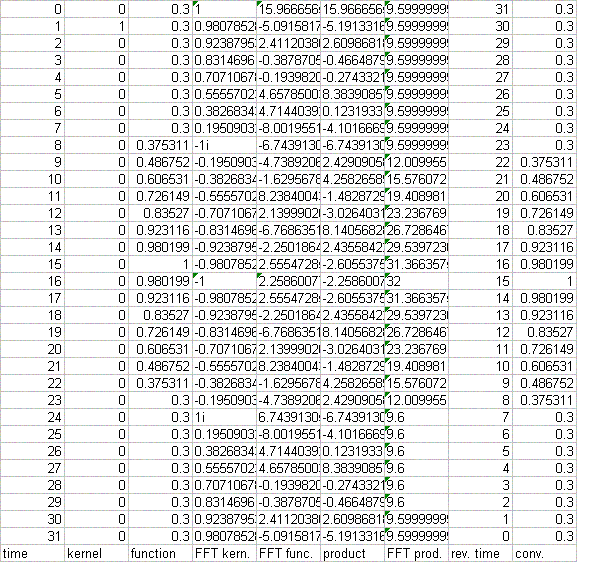
There are 32 sample points in the horizontal axis (time), with t = 0 being the first point. Thus the `A' column of the spreadsheet varies from A1 to A32 as the time varies from 0 to 31. It is seen from the right-side graph that the function remains unchanged by the delta function convolution, as expected. TABLE I is a copy of the spreadsheet used to generate the top case of Fig. 1. (Note that the column labels (A through I) and the row labels (1 through 32) are omitted from the copy.)
TABLE I. Copy of spreadsheet `code' used to generate the top case of Fig. 1.
Autofill Operation
The leftmost (A) column is the time column, for which it has been assumed that the data sampling rate corresponds to Dt = 1. To generate this time column, one enters `0' into A1 and then enters `= A1+1' into A2. Thereafter, the full A column of time values is generated as follows. Position the cursor on the data-occupied A2 (open cross with no depression of the mouse switches), and click the left mouse switch once to highlight the box (border it with a dark solid rectangle). Then move the cursor to the lower right corner of the box (location of a solid small square) where the `open' cross of the cursor becomes altered in form to a solid cross. With the solid-cross cursor displayed, and while holding the mouse left switch closed, move toward the bottom of the A column, autofilling sequentially as descent is made through each row. When the last row is filled, release the mouse switch. This `autofill' capability of Excel is the primary power behind spreadsheet generation of filters. We will see that it is used to generate many of the numbers required for filtering.
Observe that notations concerning the layout of the spreadsheet are placed at the bottom of the sheet, following the last row 32 (end of data) rather than before the first row 1 (start of data). The reason is as follows. Downward directed autofill occurs with a `sensitive dependence on initial conditions'. If the last row of numbers is encountered swiftly, then the algorithm can rapidly generate thousands of non-deletable empty spaces. Returning from the vast `land of nothingness' is `enough to make a preacher cuss'. On the other hand, autofilling upward (from bottom to top) never meets with this type of frustration.
With a 32 point transform such as the present example, where all data is visible without scrolling the sheet, the downward autofill challenge is not a serious issue. It is an issue, however, when working with truly useful, as opposed to pedagogical data sets (typically 1 K = 1024 points minimum for decent resolution).
Another label (generated by Excel) is also worthy of note. Boxes having a small triangle in the upper left corner are evidently unique to FFT's and identify those portions of the FFT which are real-only; i.e., components that have no imaginary part. It is seen in TABLE I that every component of column G, identified at the bottom by `FFT prod.' is real, which means that the product of the previous two transforms results in an even function in the time; i.e., p(-`w¢) = p(`w¢) (column F). (Note: this labeling of real components is not part of earlier versions of Excel.)
As noted above, the nature of the arrays requires that a reversed time column
be generated. In TABLE I it is the H column, 2nd from the last (right-most,
column I). It is generated by placing `= 32 - A1 - 1' in H1 and afterwards
autofilling downward through H32. The value in H1 is one less than 32 - A1
because the delta function is positioned in time at `1' rather than at `0'.
In all examples that follow, the kernels are always positioned immediately
to the right of zero, with a `0' (or near zero) for t = 0. So that the filtered
data experience no shift in time due to the convolution, it is necessary
that the reversed time column start the first row with `N - A1 - n'; where
N is the number of points in the transform (always N =
2m = integer for the FFT, m = 5, Fig. 1), and
n is the position of the maximum (mean) of the Gaussian kernal (n = 1, Fig.
1).
PEDAGOGICAL EXAMPLE OF A LOW-PASS FILTER
The bottom case of Fig. 1 illustrates the manner in which convolution by a Gaussian can smooth the sharp edges of a function. The kernel is a Gaussian and the function with the sharp edges is a pulse. As noted earlier, a delta function (infinitesimally thin Gaussian) does not alter the shape of a function through convolution. This can be understand in terms of the delta function's spectral content; i.e., the power spectrum is constant, meaning independent of frequency. As the kernel broadens, however, and high frequency components get removed from the spectrum (note earlier discussions of the uncertainty principle), the Gaussian behaves as a low-pass filter.
Several properties of filtering, in general, can be recognized from this small-sample case. Convolution can be thought of graphically as a `sliding' operation; i.e., the kernel is `folded around zero and then slid from left to right past the function. The German word for convolution, is `faltung' (folding) integral. Each time point of the slide produces an integral; so it becomes immediately obvious why the brute force calculation, as opposed to the FFT method, is prohibitive for many cases. Each integral involves the product of the function with the kernel positioned so that its mean is located at the time of interest. In other words, a given one of the N points in the convolution corresponds to a sum over the function as `modulated' (weighted) by the kernal function.
Another point is worthy of note. The folding of the kernel about zero to obtain the first point of the convolution places it in a negative time regime. From Fig. 1, it would appear that this should not be allowed by the array; however, negative values of the time are actually present in the array. All index values greater than N/2 (16 in Fig 1) are negative time values. They increase sequentially from t = -16 (corresponding to index 17) to t = -1 (index 32)
`NORMALIZATION' ISSUES
As noted earlier, the peak of the kernel is always set to unity. The kernel is generated by the autofill function in a manner analogous to the description of the generation of the column of time values. Having determined the position of the mean (A5 for the bottom case of Fig. 1), one places `exp(-c(A5-4)^2)' into the A5 box, using a first-guess value for the coefficient c. Autofilling is done both upward and downward from A5 to fill the nonzero values of the kernel column. The constant c is adjusted by trial and error (easily done with excel) until the kernel value at t = 0 is close to zero. The kernel is then symmetrized about A5 and the rest of the kernel column (zero's) are also readily generated using autofill.
PRACTICAL FILTER EXAMPLES
LOW-PASS FILTER
A folded pendulum (horizontal seismometer) built by the author had earlier recorded an earthquake in Alaska. A portion of this quake record was low-pass filtered by the same means as described in the preceding pedagogical example, except using 1024 points instead of 32. The maximum point size of FFT's used by the author has been 4096; however, 1032 is probably near optimal for spreadsheet work. (For the reasons mentioned earlier, all autofilling of columns in the downward direction were avoided as much as possible.) The filtering results are shown in Fig. 2.
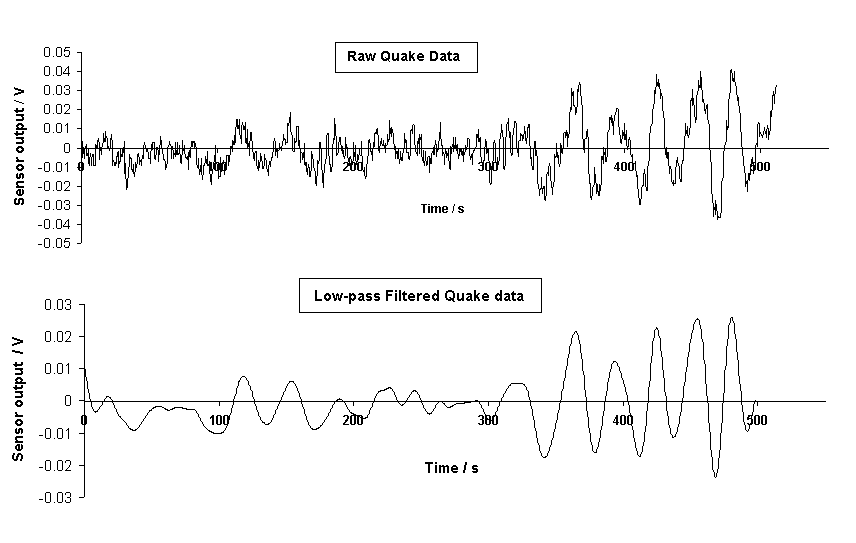
Figure 2. Example of low pass filtering of an earthquake record comprising
1024 sample points.
The Gaussian used for the convolution filtering of Fig. 2 is shown in Fig. 3, which also shows its Bode plot.
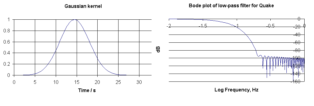
Figure 3. Gaussian kernel and associated Bode plot used for the filtering
shown in Fig. 2.
BODE PLOT
Essential characteristics of a filter are expressible in the form of a Bode plot. To generate the Bode plot, one first computes the FFT of the kernel, which was for this work printed to a separate Excel sheet. The FFT's used for filtering were all placed on the same sheet with the time and signal data. Excel allows the user to choose placement, and the generation process uses autofill naturally when working with small arrays such as the pedagogical examples. For large arrays, placement on the opening (first) sheet is accomplished more easily by autofilling only the first few boxes and then, by editorial action on the tool bar, typing in the value of the `terminal state' (such as 1024).
On the Bode plot sheet the FFT is placed by Excel default into the A column. This was moved to position E to make room for additional columns necessary for plotting. First, a frequency column was generated at A by entering `0' into A1. Then `=A1+1/(delta t x N)' (where for Fig. 3 delta t = 0.5 s & N = 1024) was entered into the 2nd row. Subsequently, the frequency column was generated by autofilling downward from A2.
Because the independent variable of the Bode plot is log(frequency), this was generated in the B column. For example, one may enter `=log(A1024)' into B1024 and then autofill upward through B1 to fill the B column.
The dependent variable values in decibels were calculated as follows by autofilling upward. Start with the following entry into D512:
`= 20*LOG(SQRT(IMREAL(E512)^2+IMAGINARY(E512)^2)/512)'
Values above D512 are not considered even though the components are generated by the algorithm; i.e., the Nyquist (maximum) frequency is at the position of the folding index N/2.
The largest value in dB's thus obtained was -31. Because it is customary to show the maximum of a Bode plot as 0, a C column was generated by adding 31 to each of the D column values.
Finally the Bode plot seen in Fig. 3 was generated by graphing Column C against column B.
BAND-PASS FILTER KERNEL
To generate the kernel for a bandpass filter, one sets the bandpass frequency by means of a cosine function. The frequencies passed are determined by the width of the Gaussian multiplying the cosine. An example is shown in Fig. 4. The kernel is the set of 100 points identified by the small solid circles. These points are `clarified' for the graph by means of the solid line passing through them, which is automatically generated by Excel through use of one of the graphing options. The cosine and Gaussian used to produce the kernel are identified by the fainter colored lines.
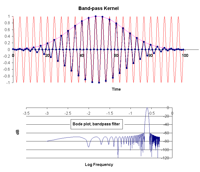
Figure 4. Kernel and associated Bode plot for an example bandpass
filter.
Designed to work with a 1024-point record, the bandpass frequency is seen from the Bode plot to be 0.25, consistent with the cosine that was generated by autofilling the `cosine column' via entry of `= cos(6.2832*A1024*256/1024)' into row 1024 and autofilling upward. (Time had already been placed in column A, with a time step of 1).
As noted, the width of the Gaussian determines the frequencies passed- the more narrow it is, the wider the bandpass. For the present case the Gaussian was generated by entering ` exp(-0.002*(A50-49)^2) ' into row 50 of the C column. Autofilling on both sides of row 50 produced the 100 non-zero values of the kernel. After generating these 100 numbers, 924 zeros were placed in the remaining rows of the column. Before graphing the B column versus the A column, the B column was autofill-generated by entering ` = D1024*C1024 into B1024.
BAND-PASS FILTER
Example use with an Earthquake Record
The spectrum generated from the raw quake record showed that the seismometer damping (provided by eddy currents generated with rare earth magnets) was not optimal (near critical). Disturbances of the instrument thus result in a transient oscillatory response corresponding to the natural period of the instrument, slightly greater than 5 s.
Both the instrument transient response and high frequency electronics noise were eliminated by the low-pass filtering that produced the lower trace of Fig. 2. In the upper (raw) trace of Fig. 2 the transient component can be seen, but its temporal dependence is not easily visualized due to the presence of the larger earthquake component having a frequency of 0.035 Hz. The 1/4 Hz component can be `pulled-out' of the spectrum by bandpass filtering, as illustrated in Fig. 5.
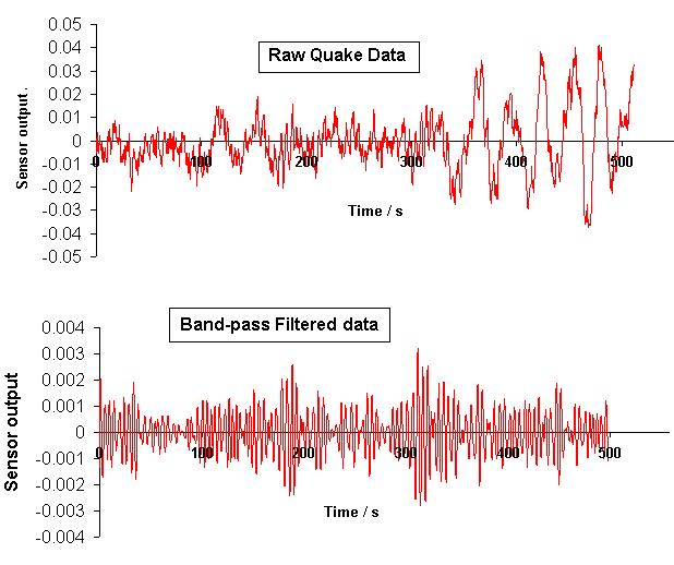
Figure 5. Band-pass filtered quake data. The frequency characteristics
of the filter are shown in the Bode plot of Fig. 6.
The kernel employed for the bandpass operation is shown, along with its Bode plot, in Fig. 6.
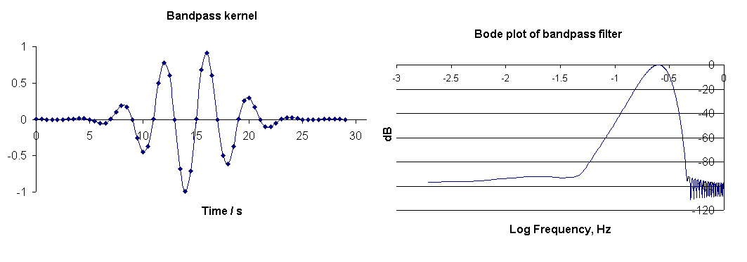
Figure 6. Kernel used for the band-pass filtering of Fig. 5, and its
associated Bode plot.
HIGH-PASS FILTERING
The generation of a high pass filter (elimination of frequencies below a `cut-on' value) is not nearly so easy as the generation of low-pass and band-pass filters. Although possible, it is not usually the simple product of a Gaussian and a cosine. To produce the kernel, the frequencies of the pass-band are first specified as an even-function column vector. Then the transform of this vector is generated to yield the kernel, which is a real function whose integral over all time vanishes because of positive and negative values. To approximate the kernel with fewer than the full N non-zero values (entering 0's at various places in the column) can seriously degrade from the intended result.
The details for generating such a filter are omitted from this article. High-pass post-processor filtering of data is infrequently needed, even though the analog electronics that generated the data may have contained such a filter. If the need exists to remove low frequencies from a record, usually a band-pass filter is adequate to the task.
BIBLIOGRAPHY
1. R. D Peters, ``Graphical explanation for the speed of the Fast Fourier Transform'', online at http://arxiv.org/html/math.HO/0302212.